Characterizing AD7746 Error Sources at −80°C: What to Fix Before Calibration
Characterizing AD7746 Error Sources at −80°C: What to Fix Before Calibration
Why Do This Before Calibration?
The previous post showed our AD7746 + P14 Rapid humidity system achieves 0.09% RH repeatability in a salt-solution chamber at room temperature. The next logical step is multi-point humidity calibration across the full flight temperature range.
But calibration built on unknown foundations is worthless. If the measurement circuit adds drift that changes with temperature, your calibration curve absorbs that drift and produces garbage when conditions change. Before spending weeks generating calibration data against salt-solution references, you need to know which error sources exist, which dominate, and which need to be fixed in hardware first.
This post is a systematic decomposition of the measurement chain — testing each layer in isolation to find where the errors come from.
The First Test: Something Is Wrong
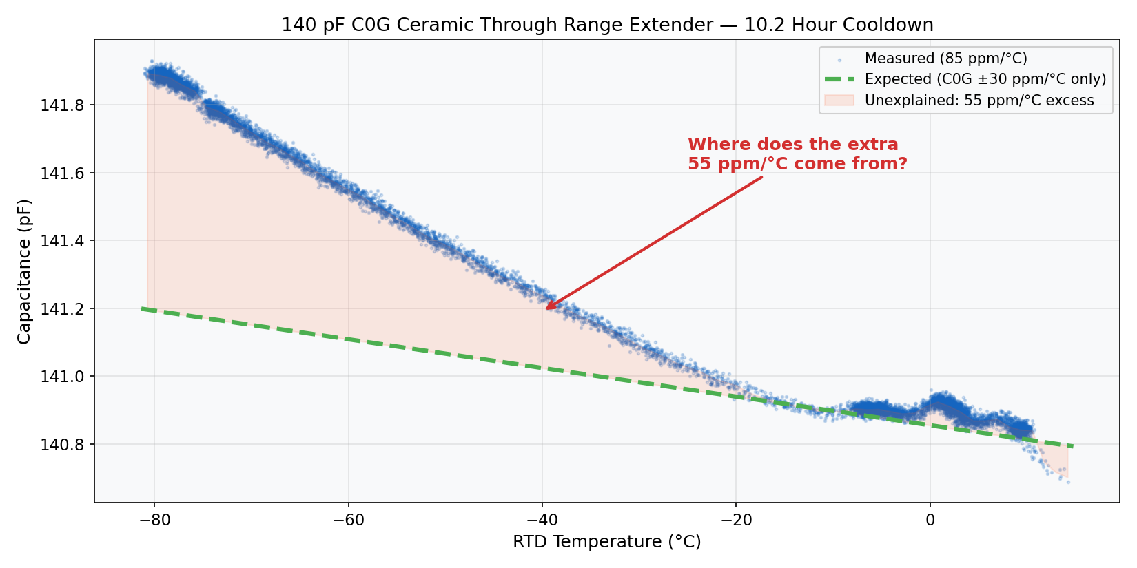
We connected a C0G/NP0 ceramic 140 pF reference capacitor — chosen because it’s close to the P14 Rapid’s nominal capacitance (~148 pF) — through the AN-1585 range extender circuit, placed the board in a Stirling free-piston cooler, and swept from +14.8°C to −81.4°C over 10.2 hours (27,671 samples).
C0G ceramics have a specified tempco of ±30 ppm/°C. For a 140 pF capacitor over an 89°C temperature swing, we expected to see about 4.2 fF/°C of drift from the ceramic alone. Here’s what we actually measured:
| Parameter | Expected | Measured |
|---|---|---|
| Drift rate | 30 ppm/°C (C0G spec) | 84.6 ppm/°C |
| fF per °C | 4.2 fF/°C | 11.9 fF/°C |
| Total ΔC over 89°C | ~375 fF | 1,065 fF |
| Ratio | 1.0× | 2.8× |
The measured drift is 2.8× higher than the ceramic capacitor alone should produce. There are 54.6 ppm/°C of unexplained drift — somewhere in the measurement chain, something is adding temperature-dependent error that the calibration would blindly absorb.
Where does it come from? There are two suspects: the AD7746 ADC, and the range extender circuit.
Isolating the ADC: Open-Circuit Plunge from +2°C to −80°C
To measure how much drift the AD7746 itself contributes, we disconnected the capacitor entirely and ran the board open-circuit through the full cooldown — from +2°C down to −80°C over 4.7 hours (3,410 samples). With nothing connected, any change in the reported capacitance comes from the ADC offset drift and range-extender parasitics — not the sensor.
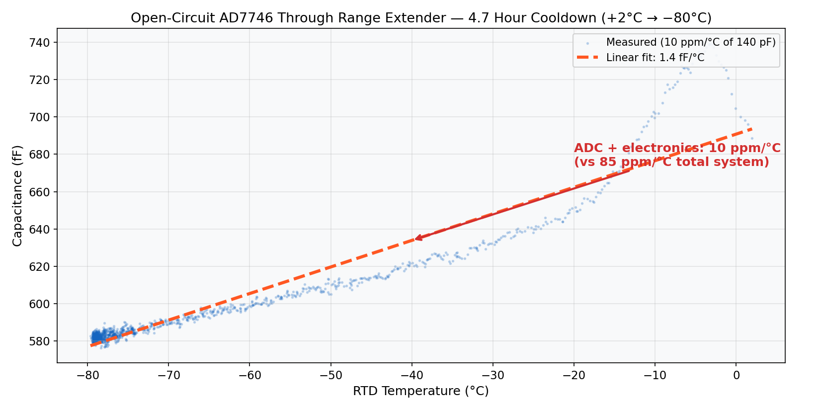
The open-circuit reading drifts from 697 fF at +2°C down to 583 fF at −80°C — a total shift of 115 fF over 79°C. But notice the direction: the open-circuit cap decreases as the board cools, while the 140 pF measurement increases with cooling. The ADC offset is drifting in the opposite direction to the system drift. Expressed as signed ppm/°C (of the 140 pF measurement, negative = cap reads higher as board cools):
| Source | dC/dT | ppm/°C (of 140 pF) | Direction |
|---|---|---|---|
| Total measured (140pF + range ext) | −11.9 fF/°C | −84.6 | cap ↑ as T ↓ |
| ADC + electronics (open circuit) | +1.45 fF/°C | +10.1 | cap ↓ as T ↓ |
| Non-electronic (total − ADC) | −13.4 fF/°C | −94.7 | |
| C0G ceramic (spec bound) | ±4.2 fF/°C | ±30 | sign unknown |
| Remaining → resistor tempco | −64.7 to −124.7 | dominates |
The signs matter. Because the ADC offset drifts in the opposite direction to the total, it was partially masking the resistor problem — making the system look better than it really is. The non-electronic drift is actually −94.7 ppm/°C. Even if the C0G ceramic contributes its full −30 ppm/°C in the same direction, the resistor divider accounts for at least −64.7 ppm/°C — worse than the unsigned ±55 ppm/°C worst-case calculation, and well within the ±100 ppm/°C thick-film rating.
ADC Noise Floor at −78°C
Once the board stabilized at −78°C, we held open-circuit for another 50 minutes (603 samples) to characterize the random noise floor:
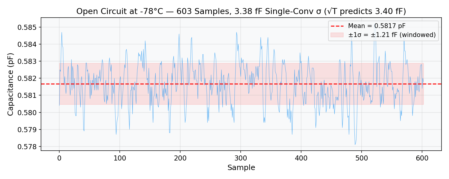
The ADC output with nothing connected is rock-solid — ±1.2 fF noise (1σ) on the averaged output. No anomalous noise sources, no cryogenic degradation.
The Range Extender: Found It
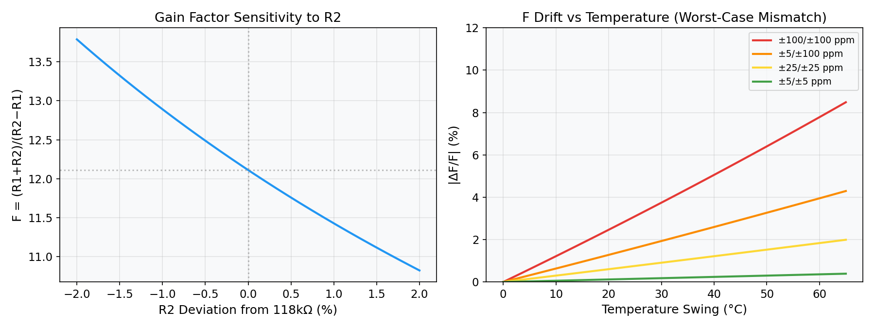
With the ADC drifting in the opposite direction (+10.1 ppm/°C) and the C0G ceramic bounded at ±30 ppm/°C, the non-electronic drift totals −94.7 ppm/°C — meaning the resistor divider contributes at least −65 ppm/°C. The AD7746’s native ±4 pF range is extended to ±48.5 pF using a resistor voltage divider on the excitation output (per Analog Devices AN-1585). The gain factor is:
\[F = \frac{R_1 + R_2}{R_2 - R_1} = \frac{100\text{k} + 118\text{k}}{118\text{k} - 100\text{k}} = 12.11\]This F factor multiplies the effective capacitance — but it also means any change in R1 or R2 with temperature directly changes the measured result. The denominator is only 18 kΩ, a small difference between two large numbers, making F catastrophically sensitive to mismatch.
The current resistors are thick-film parts rated at ±100 ppm/°C each. In the worst case (R1 and R2 drift in opposite directions), the gain factor F drifts by:
\[\frac{\Delta F}{F} \approx \frac{(TC_1 + TC_2) \times \Delta T \times (R_1 + R_2)}{R_2 - R_1}\]For ±100 ppm/°C resistors over 89°C, this produces up to ~55 ppm/°C of apparent capacitance drift (unsigned worst case). The signed analysis shows the resistors contribute at least −65 ppm/°C — exceeding the unsigned bound because the ADC’s opposing drift was partially hiding the true magnitude. This is consistent with both resistors having significant (but not maximum) tempco in the same unfavorable direction.
Random Noise: Also the Range Extender, But Manageable
The range extender also dominates the random noise budget. De-trending the 140 pF data and computing residual noise across the temperature sweep:
| Condition | Single-conv noise σ | Notes |
|---|---|---|
| Open circuit at −78°C | 3.38 fF | ADC only, matches √T |
| 140pF + range extender (warm, +9°C) | 55.3 fF | 16× ADC floor |
| 140pF + range extender (cold, −77°C) | 57.7 fF | 17× ADC floor |
The ~55 fF noise is essentially temperature-independent (cold/warm ratio 1.04), consistent with the F = 12.11 gain amplifying excitation and Johnson noise from the divider resistors. After 32× averaging this becomes ±10 fF → ±0.027 %RH — acceptable. The random noise is manageable. It’s the systematic drift that kills you.
What Needs to Change: The Resistors
At least 65 ppm/°C of the system drift — the dominant error source — comes from the thick-film range extension resistors. This drift is not calibratable because it changes with temperature during flight.
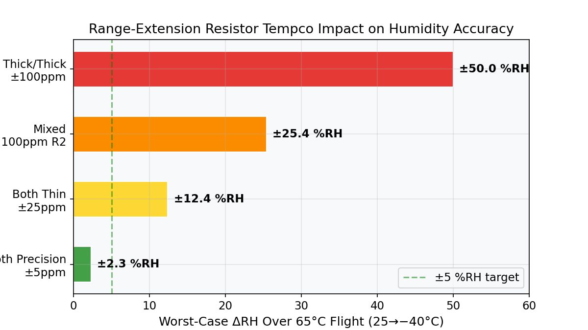
Tempco Drift Over a Flight Envelope
Board temperature swing: 95°C (from +25°C ground to −70°C in-flight), using P14 Rapid sensitivity of ~0.25 pF/%RH:
| Scenario | R1 TC | R2 TC | Worst-case ΔRH |
|---|---|---|---|
| Current (thick/thick) | ±100 ppm | ±100 ppm | ±64 %RH |
| Both thin (±25 ppm) | ±25 ppm | ±25 ppm | ±16 %RH |
| Both precision (±5 ppm) | ±5 ppm | ±5 ppm | ±3.2 %RH |
The 118 kΩ Problem
100 kΩ is readily available in precision thin film (±0.1%, ±5 ppm/°C) at 0402. But 118 kΩ is an oddball E96 value — only thick film in 0402.
| Option | Precision? | F value | Flight drift |
|---|---|---|---|
| 118 kΩ single (current) | ❌ Thick only | 12.11 | ±64 %RH |
| 120 kΩ single | ✅ Thin film | 11.00 | ±2.9 %RH |
| 100 kΩ + 18 kΩ series | ✅ Both standard | 12.11 | ±3.2 %RH |
The Path to Calibration
This error decomposition tells us the order of operations:
-
✅ ADC is trustworthy. The open-circuit plunge shows only +10.1 ppm/°C of ADC drift (opposite direction to the system), and the noise floor at −78°C is ±1.2 fF.
-
✅ Random noise is manageable. ±0.027 %RH after averaging — well below our target accuracy.
-
❌ Thick-film resistors must be replaced first. With ±64 %RH of worst-case uncalibratable drift, any multi-point calibration performed now would be invalidated the moment the board temperature changes. Fix the hardware, then calibrate.
-
After the fix: swap R1/R2 for precision thin film → re-verify noise → proceed with multi-point humidity cal against salt-solution references at multiple temperatures. The uncalibratable error drops from ±64 %RH to ±3 %RH.
The lesson: characterize the electronics before calibrating the sensor. Two $0.01 thick-film resistors would have silently destroyed every calibration point.
Previous: Precision Humidity Sensing for Stratospheric Flight