Stratosonde Power Budget Calculator
🎧 Listen to this article: NotebookLM Podcast
An AI-generated audio discussion created by Google’s NotebookLM
Introducing the Stratosonde Power Budget Calculator
I’m excited to announce the launch of our comprehensive Power Budget Calculator for the Stratosonde project—an interactive tool designed to help you balance power consumption, solar harvesting, and battery capacity for ultra-lightweight, solar-powered radiosondes operating in extreme high-altitude environments.
The Power Challenge: Surviving at the Edge of Space
Designing a radiosonde that can survive days or weeks at 40,000 feet presents unique power management challenges that go far beyond typical electronics design:
Extreme Temperature: At -50°C, lithium titanate (LTO) batteries lose up to 50% of their capacity, and internal impedance skyrockets to ~2Ω (compared to ~0.4Ω at room temperature), causing significant voltage droop during peak current operations.
Limited Solar Input: Small solar panels (53x19mm wafers) producing only 0.5V at 50mA must be carefully managed through boost converters to charge higher-voltage battery packs.
Strict Weight Constraints: Every component must be optimized for minimal mass—the entire system targets under 15 grams including battery, sensors, radio, and solar panels.
Intermittent Connectivity: The radiosonde must operate autonomously for extended periods, duty-cycling all components to maximize battery life while maintaining sufficient update rates for atmospheric data collection.
This calculator helps you navigate these trade-offs and design a system that can actually survive and operate in these extreme conditions.
Understanding the Power Architecture
The calculator includes detailed system diagrams that illustrate how power flows through the Stratosonde:
Power Distribution Block Diagram
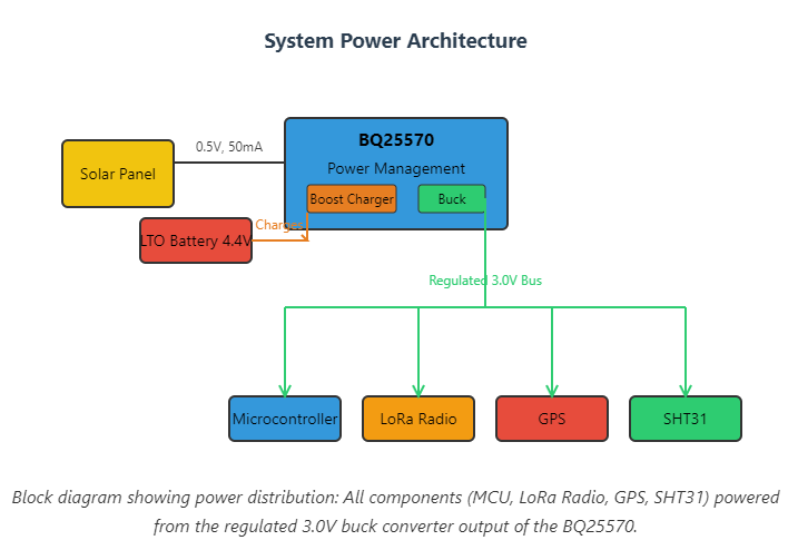
The system uses a BQ25570 energy harvester IC as the central power management component:
- Solar Input: Multiple 0.5V solar panel wafers connected in series provide 1.0V+ input
- Boost Charger: Converts low solar voltage up to 4.4V to charge the 2S LTO battery pack
- Buck Converter: Provides regulated 3.0V rail for all system components (MCU, LoRa, GPS, sensors)
- LTO Battery: 2-cell series configuration (4.4V nominal) provides energy storage
Unlike many designs that power components directly from battery voltage, the Stratosonde uses a buck converter to provide a stable 3.0V rail. This ensures all components receive consistent voltage despite battery level fluctuations and cold-temperature voltage sag.
Operation Sequence Diagram
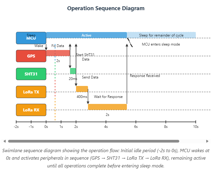
The calculator shows the precise timing of operations during each telemetry cycle:
- Sleep Period (-2s to 0s): All components in low-power mode, battery slowly recovering from previous cycle
- GPS Acquisition (0s to 2s): GPS module powers up and obtains a hot fix (~2 seconds with backup power)
- Sensor Reading (2s to 2.02s): SHT31 temperature/humidity sensor performs one-shot measurement (20ms)
- LoRa Transmission (2.02s to 2.42s): LoRaWAN packet transmitted (400ms)
- Receive Window (2.42s to 4.2s): LoRa radio listens for gateway response (1.8s)
- Return to Sleep (4.2s+): MCU and all peripherals enter deep sleep until next cycle
The MCU remains active throughout all peripheral operations, coordinating the sequence before returning to sleep.
Configuration Parameters
The calculator provides detailed control over every aspect of the power system:
System Configuration
- Update Interval: How often telemetry cycles occur (default: 5 minutes)
- Simulation Duration: Length of battery simulation (1-30 days)
- Daylight Hours: Expected sunlight per day for solar charging calculations
Battery Properties
- Battery Model: Choose from HTC1015 (40mAh), HTC1020 (50mAh), or HTC1030 (100mAh)
- Cell Configuration: Single cell (2.2V) or 2S series (4.4V)
- Cold Derating: Capacity reduction at -50°C (default: 50%)
- Internal Impedance: Resistance at cold temperature (default: 2000mΩ)
The cold derating factor is critical—LTO batteries can lose half their capacity at extreme cold, dramatically affecting mission duration calculations.
Energy Harvester (BQ25570)
- Charge Boost Efficiency: Efficiency of low-voltage to battery-voltage conversion (70%)
- Buck Converter Efficiency: Efficiency of battery to 3.0V conversion (95%)
- Quiescent Current: Continuous current draw of power management IC (0.9µA)
Solar Panel Configuration
- Panel Count: Number of 0.5V wafers in series (default: 2 = 1.0V)
- Single Panel Output: Current and voltage ratings per wafer
- Positioning Factor: Accounting for non-optimal orientation (80%)
Component Power Profiles
Each component can be configured with:
- Sleep current (microamps)
- Active current (milliamps)
- Active duration per cycle
- Operational frequency (every N cycles)
Default Component Values:
- MCU: 10µA sleep, 10mA active for 500ms
- GPS: 20µA sleep, 30mA active for 2s (hot fix)
- SHT31: 0.5µA sleep, 1mA active for 20ms
- LoRa TX: 2µA sleep, 118mA active for 400ms
- LoRa RX: 2µA sleep, 6.7mA active for 2s
Power Budget Analysis
The calculator performs comprehensive power analysis:
Energy Balance Calculation
The tool calculates:
- Total Average Current: Across all components considering duty cycles
- Daily Energy Consumption: Total mAh consumed per 24-hour period
- Daily Solar Generation: Energy harvested from solar panels
- Energy Balance: Surplus or deficit (positive = sustainable, negative = battery drain)
- Battery Life Without Solar: How long the system runs on battery alone
Component Breakdown
A detailed table shows each component’s contribution:
- Average current draw
- Daily energy consumption
- Percentage of total power budget
This helps identify power-hungry components and optimization opportunities.
Visualizations
Power Consumption Distribution (Pie Chart)
Visual breakdown of where power goes—typically showing:
- LoRaWAN radio: Largest consumer despite short duty cycle (high TX current)
- GPS: Significant when active (30mA for 2 seconds)
- MCU: Constant but low baseline
- Sensors: Minimal power draw
- BQ25570: Negligible quiescent current
Battery Capacity Over Time (Timeline Chart)
Shows hour-by-hour battery level simulation over multiple days:
- Blue line: Actual battery capacity accounting for cold derating
- Yellow overlay: Solar charging periods (daylight hours)
- Red dashed line: Room temperature capacity for reference
This visualization reveals:
- Whether the system maintains positive energy balance
- Impact of day/night cycles
- Long-term sustainability
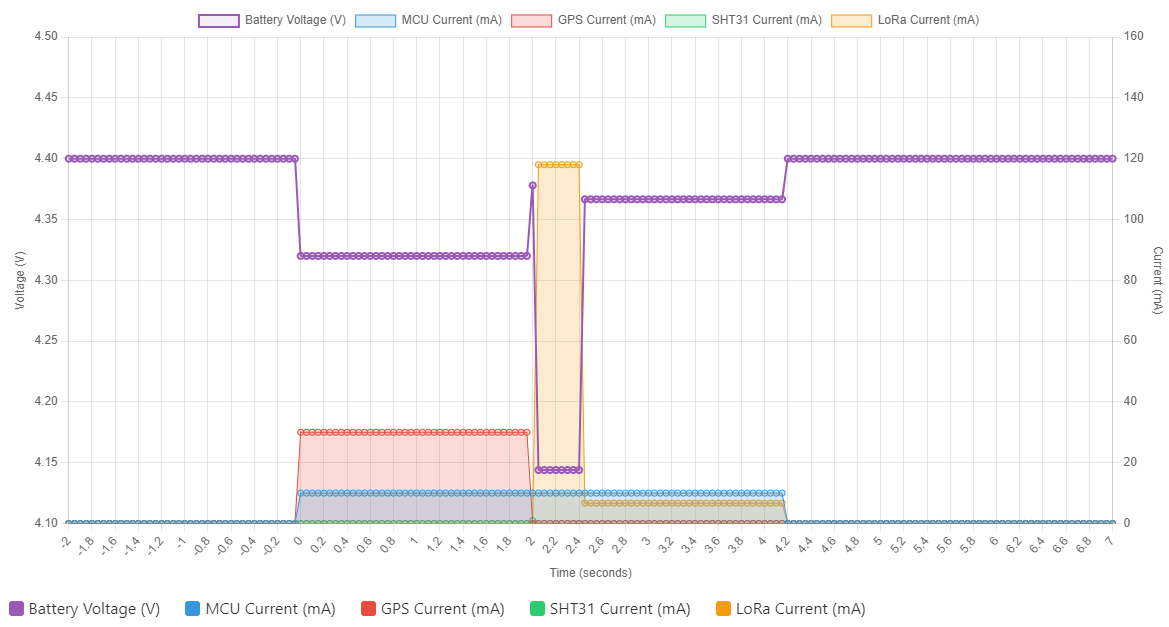
Battery Voltage During One Cycle (Voltage Droop Chart)
Critical analysis showing voltage sag due to internal impedance:
- Purple line: Actual battery terminal voltage
- Colored areas: Current draw from each component (stacked)
At -50°C with 2Ω internal resistance, high current draws (LoRa TX at 118mA) cause significant voltage drops. This chart helps verify that voltage never drops below component minimums (typically 3.0V for MCU, sensors).
Weight Budget Summary
Since every gram matters for balloon-launched systems, the calculator includes a complete weight breakdown:
- LTO Battery cells
- Solar panels
- Microcontroller/LoRa module (Wio E5)
- GPS module
- Environmental sensors
- BQ25570 power management
- PCB, antenna, and harnessing
Target: Under 15 grams total system weight
Real-World Design Example
Let’s walk through a practical configuration:
Goal: 3-day autonomous operation at 40,000 feet with 5-minute update intervals
Configuration:
- 2x HTC1015 batteries in series (40mAh @ 4.4V, ~5g)
- 50% cold derating = 20mAh effective capacity
- 2x solar panels (1.0V @ 50mA = 50mW)
- 12 hours daylight, 80% positioning factor
- Standard component power profiles
Results:
- Daily consumption: ~8.5mAh
- Daily solar generation: ~6.8mAh
- Energy deficit: -1.7mAh/day
- Battery life: 2.4 days from full charge
This configuration would require switching to HTC1030 (100mAh) batteries or reducing update frequency to achieve the 3-day goal.
Key Design Insights
Through experimentation with the calculator, several critical insights emerge:
1. Cold Temperature Dominates
The 50% capacity derating at -50°C is the single biggest challenge. Even doubling battery capacity at room temperature only provides limited improvement in extreme cold.
2. LoRa TX is the Power Hog
Despite operating for only 400ms per cycle, the 118mA transmission current makes LoRa the dominant power consumer. Reducing update frequency has outsized impact.
3. Solar Helps But Can’t Carry It Alone
With tiny panels and positioning losses, solar typically provides 60-80% of daily needs. Battery capacity remains essential for night operation and weather variability.
4. Voltage Droop Requires Margin
The 2Ω internal resistance causes significant voltage sag during peak currents. System design must ensure minimum voltages are never violated, requiring voltage margin in battery selection.
5. Every Gram Counts
At 15g total system weight, battery weight alone can be 5g+. Optimizing every component for weight-to-performance ratio is essential.
Use Cases
This calculator is valuable for:
- System Design: Evaluate different battery and solar panel combinations
- Component Selection: Compare power impact of different radios, GPS modules, sensors
- Mission Planning: Determine realistic flight durations and update intervals
- Trade-off Analysis: Balance power, weight, and performance requirements
- Failure Analysis: Understand why existing designs failed to meet duration goals
Design Foundations
This calculator is based on:
- Component datasheet specifications and characterization measurements
- Published research on cold-temperature battery performance
- Solar panel modeling and positioning analysis
- Power management IC application notes (BQ25570)
- Community knowledge from the picoballoon and amateur radio communities
What’s Next
The calculator continues to evolve based on field data and user feedback. Potential future enhancements:
- Additional battery chemistry support (LiPo, primary lithium)
- Temperature-dependent efficiency curves
- Altitude-dependent solar intensity
- Multi-day weather pattern simulation
- Export reports for documentation
- Component database for quick selection
Getting Started
Visit the Power Budget Calculator and start by:
- Selecting your battery model and configuration
- Configuring your solar panel array
- Adjusting component power profiles if using different parts
- Setting your desired update interval
- Running the simulation to check sustainability
Look for:
- ✅ Positive energy balance: Sustainable configuration
- ⚠️ Small deficit: May work in favorable conditions
- 🛑 Large deficit: Redesign required
Acknowledgments
This tool builds on power management best practices from:
- High-altitude balloon community flight data
- BQ25570 application notes and design tools
- LTO battery manufacturer specifications
- Real-world measurement of component power consumption
Special thanks to the picoballoon and amateur radio communities for sharing their extensive experience with long-duration, solar-powered flights.
For More Information
To learn more about the Stratosonde project:
- Project Specification - Complete hardware and firmware requirements
- Power Management Documentation - Detailed firmware implementation
Happy calculating, and may your radiosondes fly long and far!