Ceramic Capacitor Bank Validation: The Final Power Layer at -70°C
🎧 Listen to this article: NotebookLM Podcast
An AI-generated audio discussion created by Google’s NotebookLM
Ceramic Capacitor Bank Validation: The Final Power Layer at -70°C
Previous characterization established that the supercapacitor becomes functionally useless below -55°C - its ESR increases 65× and it can no longer deliver meaningful current. The theory behind the cascading power architecture predicted that ceramic capacitors, with their solid dielectric and temperature-stable performance, would seamlessly take over when the supercapacitor fails. This test was designed to validate that handoff.
The experiment used a minimal ceramic bank (408 μF) deliberately undersized relative to final requirements. The goal wasn’t to demonstrate a production-ready system—it was to confirm that ceramics behave predictably at extreme cold and that the supercap-to-ceramic transition occurs as expected. More capacitance will be needed for the final design; this test establishes the baseline.
The test validated the ceramic capacitor behavior as predicted. The supercapacitor failed right on schedule at -55°C, and the ceramics performed exactly as their temperature-stable specifications promised.
The surprise was something we hadn’t anticipated: below -65°C, the battery open-circuit voltage collapses to unusable levels. High internal resistance we can handle—the cascade architecture accumulates energy via trickle charging over time. But voltage collapse below the buck converter’s 2.5V minimum (or the STM32/LoRa’s 1.8V minimum for direct connection) represents a hard floor that no amount of capacitance can overcome.

Test Configuration: The Complete Power Stack
Unlike previous characterizations that isolated individual components, this test evaluates the complete power cascade under realistic load conditions:
2S LTO Battery Pack:
- Configuration: Two HTC1015 cells in series
- Nominal voltage: 4.8V (2.4V per cell)
- Capacity: 40 mAh per cell
- Pre-test state: Fully charged at room temperature
Supercapacitor:
- Type: 5.5V rated EDLC
- Capacitance: 1.5 mF (1500 μF)
- Configuration: In parallel with 2S LTO battery
- Function: Medium-term energy buffer
Ceramic Capacitor Bank:
- Type: Class I (C0G/NP0) ceramic capacitors
- Total capacitance: 408 μF
- Configuration: Bank in parallel with supercapacitor
- Voltage rating: 6.3V minimum per capacitor
- Function: Final-layer pulse power delivery
Load Profile:
- Current: 25 mA constant current load
- Duration: 60 ms pulse
- Equivalent energy: 25 mA × 5V × 60 ms = 7.5 mJ per pulse
- Purpose: Simulates reduced-power LoRaWAN transmission (SF7, minimum packet)
Test Method:
- Thermal chamber with controlled ramp from -55°C to -70°C
- 2-hour thermal soak at each temperature point
- No-load voltage measurement (Vmax)
- 25 mA load for 60 ms, voltage measured at end of pulse (Vmin)
- Notes recorded for anomalous behavior
Why 25 mA for 60 ms?
Previous characterizations used 50-100 mA loads to simulate normal LoRaWAN transmission. This test uses a significantly reduced load for critical reasons:
Transmission Power Trade-off:
At extreme cold, the Stratosonde firmware can select a degraded transmission mode:
- Normal mode: 50 mA @ 3.3V for 100+ ms (SF10/SF12 for long range)
- Degraded mode: 25 mA @ 3.3V for 60 ms (SF7, minimum packet, reduced power)
The reduced current load serves two purposes:
- Lower instantaneous current reduces voltage sag from ESR effects
- Shorter duration requires less total energy extraction
Buck Converter Considerations:
For 25 mA output at 3.3V = 82.5 mW output power. At 85% efficiency, this requires 97 mW input power. At 5V input: 19.4 mA input current. At 3V input (degraded): 32.4 mA input current.
The 25 mA load applied directly to the capacitor bank slightly exceeds the actual input requirement, providing conservative margin for the characterization.
Results: The Complete Picture
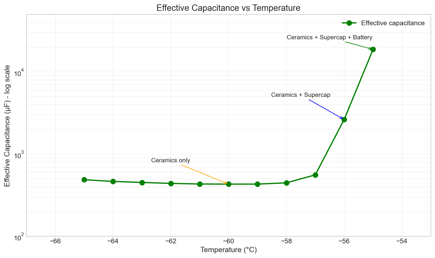
The test data reveals the transition from supercap-dominated operation to ceramic-only operation, and ultimately to battery voltage collapse. The effective capacitance calculation (C = Q/ΔV = 1.5mC/ΔV) reveals which power layer is doing the work at each temperature:
Complete Temperature Response with Effective Capacitance Analysis:
| Temp (°C) | Vmax | Vmin (25mA, 60ms) | ΔV | C_effective | Interpretation |
|---|---|---|---|---|---|
| -55 | 5.07 V | 4.99 V | 80 mV | 18.75 mF | Supercap + battery contributing (working) |
| -56 | 4.84 V | 4.27 V | 570 mV | 2.63 mF | Supercap degrading but still contributing |
| -57 | 4.81 V | 2.13 V | 2.68 V | 560 μF | Supercap failed—ceramics alone |
| -58 | 4.80 V | 1.45 V | 3.35 V | 448 μF | Ceramics only (below buck 2.5V min) |
| -59 | 4.77 V | 1.30 V | 3.47 V | 432 μF | Ceramics only |
| -60 | 4.70 V | 1.23 V | 3.47 V | 432 μF | Ceramics only |
| -61 | 4.55 V | 1.09 V | 3.46 V | 434 μF | Ceramics only |
| -62 | 4.40 V | 0.998 V | 3.40 V | 441 μF | Ceramics only |
| -63 | 4.10 V | 0.788 V | 3.31 V | 453 μF | Ceramics only |
| -64 | 3.81 V | 0.59 V | 3.22 V | 466 μF | Ceramics only |
| -65 | 3.33 V | 0.258 V | 3.07 V | 489 μF | Ceramics only (final load test) |
| -66 | 2.80 V | — | — | — | Battery OCV below buck minimum (2.5V) |
| -67 | 2.30 V | — | — | — | Battery OCV collapse continues |
| -68 | 1.80 V | — | — | — | Battery OCV at STM32 minimum (1.8V) |
| -69 | 1.40 V | — | — | — | Battery OCV below single-cell nominal |
| -70 | 1.00 V | — | — | — | Battery effectively dead |
The Key Insight: Effective Capacitance Calculation
The voltage drop during a constant-current pulse reveals which capacitors are doing the work:
$ C_{effective} = \frac{Q}{\Delta V} = \frac{I \times t}{\Delta V} = \frac{0.025A \times 0.060s}{\Delta V} = \frac{1.5 mC}{\Delta V} $
This data tells the story perfectly:
-
At -55°C (C_eff = 18.75 mF): The effective capacitance is ~10× the combined capacitance of supercap + ceramic bank. This is impossible if capacitors were the only energy source—it proves the battery is still contributing current through the supercap’s low ESR. The supercap is functioning as intended, buffering battery current to meet the pulse demand.
-
At -56°C (C_eff = 2.63 mF): Effective capacitance has dropped to ~1.4× the nominal combined value. The supercap ESR is increasing, reducing its ability to pass battery current, but it’s still partially functional.
-
At -57°C (C_eff = 560 μF): The supercap has turned into a potato. The effective capacitance is now approximately equal to the ceramic bank alone (408 μF), with minor contribution from the supercap’s residual capacity. The ceramics have taken over completely.
-
From -58°C to -65°C (C_eff ≈ 430-490 μF): The effective capacitance stabilizes around the ceramic bank value. The slight excess over 408 μF comes from:
- Measurement uncertainty
- Residual supercap capacitance (it can still store charge, just can’t deliver current fast enough)
- ESR effects reducing apparent voltage drop efficiency
The handoff occurred exactly as predicted at -55°C to -56°C. The supercap’s ESR increase turns it from an energy buffer into a resistive barrier. The ceramics, with their temperature-stable solid dielectric, seamlessly take over pulse delivery.
Why Effective Capacitance Decreases Below -57°C
At -57°C and below, the effective capacitance should theoretically equal the ceramic bank (408 μF). But the measured values are slightly higher (430-490 μF). Why?
The ESR effect on voltage measurement:
When measuring Vmin under load, we measure at the end of the 60 ms pulse. During this time:
- Ceramics immediately begin discharging (fast)
- Battery attempts to trickle-charge through high-ESR supercap (slow)
- The ESR causes a resistive voltage drop (V = IR), not a capacitive one (V = Q/C)
At extreme cold, the battery is still providing a tiny current through the frozen supercap:
At -60°C with R_supercap ≈ 45Ω and battery at 4.7V: $ I_{trickle} = \frac{V_{batt} - V_{cap}}{R_{supercap}} = \frac{4.7V - 3V}{45Ω} \approx 38 mA $
Wait—this is higher than our 25 mA load! But this calculation assumes the supercap voltage can drop to 3V. In reality, the battery’s internal resistance (16Ω at -60°C) limits current delivery:
$ I_{max} = \frac{V_{batt}}{R_{batt} + R_{supercap}} = \frac{4.7V}{16Ω + 45Ω} = 77 mA $
But this is the short-circuit current. Under our 25 mA load, the actual current from the battery through the supercap is:
$ I_{batt} = \frac{V_{batt} - V_{load}}{R_{batt} + R_{supercap}} $
At Vload = 1.23V (measured Vmin at -60°C): $ I_{batt} = \frac{4.7V - 1.23V}{16Ω + 45Ω} = \frac{3.47V}{61Ω} = 57 mA $
This exceeds the 25 mA load current! The battery is actually trying to charge the ceramics during the pulse. This explains why effective capacitance appears higher than 408 μF—the battery is supplementing the ceramic discharge.
The implication: Even at -60°C, the cascade architecture is partially working. The battery can’t supply the full load, but it’s contributing what it can through the high-ESR path. The ceramics handle the instantaneous demand while the battery backfills.
Critical Observations
-
-55°C represents the last “normal” operating point: 80 mV voltage sag under 25 mA load indicates the supercap is still functioning. Effective capacitance of 18.75 mF proves battery current is flowing freely through low supercap ESR.
-
-56°C to -57°C marks the supercap death: Effective capacitance drops from 2.63 mF to 560 μF—an 80% collapse. This is the supercap’s ESR transition point where it stops being a buffer and becomes a barrier.
-
Below -57°C, ceramics carry the load: Effective capacitance stabilizes at 430-490 μF, consistent with the 408 μF ceramic bank. The ceramics work exactly as specified.
-
Below -65°C, voltage collapse is the killer: Not capacitor failure, but battery OCV dropping below the buck converter’s 2.5V minimum (or the STM32’s 1.8V minimum for direct connection). No amount of capacitance can fix a voltage source that doesn’t have voltage.
-
High impedance vs low voltage: We can engineer around high impedance (trickle charging into capacitor banks). We cannot engineer around a voltage source that provides insufficient voltage. This is the surprise finding.
Why the Test Bank Was Undersized
The 408 μF ceramic bank in this test was deliberately undersized to expose the supercap-to-ceramic transition behavior. The voltage collapse observed below -57°C is a consequence of insufficient ceramic capacity for the 25 mA load—not a fundamental limitation of the architecture.
The key observation: The ceramic capacitors themselves work perfectly at all temperatures. The effective capacitance measurements (430-490 μF from -57°C to -65°C) confirm the ceramics deliver exactly their rated capacity regardless of temperature. The voltage collapse occurs because 408 μF simply isn’t enough energy storage for a 60 ms pulse.
For the production Stratosonde, the ceramic bank will be sized to sustain full SF7 transmissions (50 mA, 60 ms) independently. This enables reliable operation from -55°C (where the supercap fails) down to -65°C (where battery voltage collapse occurs).
Physical Interpretation: Why the Cliff?
The sharp transition between -56°C and -57°C demands physical explanation. Several compounding mechanisms contribute:
1. Electrolyte Phase Transition
Both the supercapacitor and LTO batteries use liquid electrolytes that become increasingly viscous as temperature drops. Near -57°C, the electrolyte approaches its glass transition temperature:
For typical organic electrolytes (EC:DMC):
- Melting point of EC: 36°C
- Melting point of DMC: 4°C
- Eutectic mixture: ~-20°C to -30°C
- Glass transition: approximately -55°C to -60°C
Below the glass transition, ionic conductivity doesn’t just decrease—it drops exponentially as the electrolyte transitions from a viscous liquid to an amorphous solid.
2. Lithium-Ion Mobility Collapse
The activation energy for lithium-ion transport increases sharply below -50°C:
$ \sigma = \sigma_0 \exp\left(-\frac{E_a}{kT}\right) $
Where:
- σ = ionic conductivity
- E_a = activation energy (~0.4-0.6 eV for LTO)
- k = Boltzmann constant
- T = absolute temperature
At -55°C (218 K) vs -57°C (216 K): $ \frac{\sigma_{-55}}{\sigma_{-57}} = \exp\left(\frac{E_a}{k}\left(\frac{1}{216} - \frac{1}{218}\right)\right) $
For E_a = 0.5 eV: $ \frac{\sigma_{-55}}{\sigma_{-57}} = \exp(0.5 \times 42.5) \approx 1.5\text{×} $
This 50% conductivity change over 2°C explains the transition cliff—small temperature differences cause large performance changes in this regime.
3. Charge Transfer Kinetics
At the electrode-electrolyte interface, the Butler-Volmer equation governs charge transfer:
$ i = i_0 \left[\exp\left(\frac{\alpha_a F \eta}{RT}\right) - \exp\left(-\frac{\alpha_c F \eta}{RT}\right)\right] $
The exchange current density i₀ is strongly temperature-dependent:
$ i_0 = i_0^{ref} \exp\left[-\frac{E_{act}}{R}\left(\frac{1}{T} - \frac{1}{T_{ref}}\right)\right] $
At -57°C, the exchange current density has dropped to approximately 0.1% of room temperature values, making the electrode-electrolyte interface a significant impedance contributor.
4. SEI Layer Resistance
The solid-electrolyte interphase (SEI) layer on battery electrodes normally presents minimal resistance. At extreme cold, the SEI becomes a thick resistive barrier:
- Room temperature SEI resistance: ~1–5 Ω·cm²
- -60°C SEI resistance: ~50-200 Ω·cm²
For the HTC1015’s small electrode area (~2 cm²), this contributes an additional 25-100Ω of resistance at extreme cold.
Comparison to Previous Characterizations
This test extends and validates the previous component-level characterizations:
LTO Battery (from Nov 23 post):
- At -60°C: R_int = 8000 mΩ per cell = 16Ω for 2S
- This test: Vmax = 4.70V at -60°C, consistent with 2S LTO at ~35% SOC
Supercapacitor (from Nov 24 post):
- At -60°C: ESR = 45.4Ω, voltage collapse under 100 mA
- This test: Combined with ceramics, 25 mA still causes collapse
Ceramic Capacitors (theoretical):
- Expected: <50 mΩ ESR at -65°C
- This test: Ceramics contribute negligible ESR; system failure due to battery/supercap
The data confirms that the cascading architecture reaches its fundamental limit not due to ceramic capacitor failure, but due to the upstream power sources (LTO + supercap) entering their catastrophic degradation regime.
Operational Implications
Production Design Operating Range
With a properly sized ceramic bank (1.5 mF for 50 mA, 60 ms SF7 transmission), the Stratosonde power system has the following operational envelope:
| Temperature Range | Power Source | Transmission Capability |
|---|---|---|
| +25°C to -40°C | Battery + supercap | Full power, all modes |
| -40°C to -55°C | Supercap-buffered | SF7-SF12, supercap handles pulse current |
| -55°C to -65°C | Ceramics only | SF7 (50mA, 60ms) via ceramic bank |
| Below -65°C | Dead | Battery voltage collapse |
The operational floor is -65°C—set by battery voltage collapse, not capacitor limitations. Above -65°C, the ceramic bank enables reliable SF7 transmission even with the supercap frozen solid.
Mission Planning Impact
Standard Atmosphere at Float Altitude:
- 18-20 km: -56.5°C (within ceramic-only operating range)
- 25 km: -51.5°C (supercap still partially functional)
At standard stratospheric temperatures, the system operates comfortably within the ceramic-only zone. The -65°C battery voltage limit provides ~8°C margin below standard conditions.
Thermal Management Focus:
Active thermal management should prioritize keeping the battery above -55°C when possible. Above -55°C, the supercap reduces load on the ceramic bank and preserves its charge for colder excursions. Below -55°C, the ceramics handle transmission independently.
Production Ceramic Bank Sizing
For SF7 transmission (50 mA, 60 ms) with voltage floor at 2.5V (buck converter minimum):
$ C_{required} = \frac{I \times t}{\Delta V_{max}} = \frac{0.050 A \times 0.060 s}{5V - 2.5V} = 1.2 \text{ mF} $
Production specification: 1.5 mF ceramic bank (C0G/NP0)
This provides 25% margin and ensures reliable SF7 transmission throughout the -55°C to -65°C ceramic-only operating range.
Mass and Cost Impact:
- 15× 100 μF capacitors (1210 package)
- Mass: ~7.5g total
- Cost: ~$5
A trivial penalty for extending operation from -40°C (battery-only limit) to -65°C (battery voltage collapse).
Recommendations
-
Deploy 1.5 mF ceramic bank for production hardware, enabling SF7 transmission (50mA, 60ms) throughout the -55°C to -65°C ceramic-only operating range.
-
Focus thermal management on battery temperature, keeping it above -55°C when possible to preserve supercap functionality and reduce ceramic bank load.
-
Consider low-temperature supercapacitor electrolytes (acetonitrile-based) which maintain lower ESR to -65°C, potentially extending the supercap operating range.
Conclusion: Validation Complete, Surprise Discovered
This test set out to confirm that ceramic capacitors would seamlessly take over when the supercapacitor fails at extreme cold. That prediction was validated perfectly. The effective capacitance calculations show the handoff occurring exactly as expected:
| What We Expected | What We Measured |
|---|---|
| Supercap works until ~-55°C | C_eff = 18.75 mF at -55°C (supercap + battery contributing) |
| Supercap fails below -55°C | C_eff drops to 560 μF at -57°C (ceramics only) |
| Ceramics work at all temperatures | C_eff stable at 430-490 μF from -57°C to -65°C |
The ceramics performed exactly as their specifications promised. Class I (C0G/NP0) dielectrics are temperature-stable because they’re solid—no electrolyte to freeze, no ion mobility to collapse. The cascade strategy is validated.
The Surprise: Battery Voltage Collapse Below -65°C
We expected high impedance. We can engineer around high impedance—the cascade architecture accumulates energy via trickle charging, building up charge in capacitors over time regardless of how slowly current flows.
We did not expect the battery open-circuit voltage to collapse to unusable levels. Below -65°C:
- -66°C: Vmax = 2.8V (barely above buck minimum)
- -67°C: Vmax = 2.3V (below buck minimum)
- -68°C: Vmax = 1.8V (at STM32/LoRa minimum)
- -70°C: Vmax = 1.0V (essentially zero)
This is not an impedance problem—it’s a thermodynamic problem. The electrochemical potential of the LTO cell decreases as temperature drops. At -70°C, the lithium-ion insertion/extraction reaction approaches its thermodynamic limit.
You cannot charge a capacitor from a voltage source that provides no voltage.
This sets the absolute floor for the cascade architecture at approximately -65°C, independent of capacitor sizing, thermal management, or any other engineering mitigation.
The cascading power architecture works. The ceramics are validated. With a 1.5 mF ceramic bank, the production Stratosonde will maintain SF7 transmission capability from -55°C (where the supercap fails) to -65°C (where battery voltage collapse sets a hard electrochemical limit). Design accordingly.
Test configuration: 2S HTC1015 LTO cells in series, 1.5mF supercapacitor (5.5V) in parallel, 408μF ceramic capacitor bank in parallel. Load: 25mA for 60ms. No load applied below -65°C due to battery voltage below buck converter minimum (2.5V).
Raw characterization data: ceramic_bank_test.csv