Aluminum Polymer Capacitor Integration: Bridging the Supercap-Ceramic Gap
🎧 Listen to this article: NotebookLM Podcast
An AI-generated audio discussion created by Google’s NotebookLM
Aluminum Polymer Capacitor Integration: Bridging the Supercap-Ceramic Gap
The cascading power architecture prescribes four layers: solar → LTO battery → supercapacitor → ceramic capacitors. But field testing revealed a gap: the supercapacitor fails at -55°C, yet the ceramic bank is sized only for minimum viable transmission (60ms SF7 pulses). Between these extremes lies a regime where we need more capacitance than ceramics provide but less ESR than the frozen supercap allows.
The solution: add a 3300µF aluminum polymer capacitor in parallel with the 1.5F supercapacitor. Aluminum polymer technology offers a sweet spot—moderate capacitance (3300µF vs 1.5F for supercap, vs ~1mF for ceramics) with solid polymer electrolyte that doesn’t freeze like the organic electrolyte in EDLCs.
This characterization validates the aluminum polymer integration by testing the complete hybrid stack: 2× HTC1015 LTO cells in series, 1.5F supercapacitor, and 3300µF aluminum polymer capacitor—all in parallel. The test uses two pulse profiles to separately characterize capacitive behavior (60ms pulses) and ESR-dominated behavior (2s pulses), revealing exactly when each component takes over.
Why Aluminum Polymer?
Aluminum polymer capacitors use conductive polymer as the cathode instead of liquid electrolyte:
| Property | EDLC Supercap | Aluminum Polymer | Ceramic (MLCC) |
|---|---|---|---|
| Capacitance | 0.1-10F | 10-1000µF | 1-100µF |
| Voltage | 2.7-5.5V | 2-25V | 6.3-50V |
| ESR (25°C) | 10-500mΩ | 5-50mΩ | <10mΩ |
| ESR (−60°C) | 10-100Ω (catastrophic) | 50-200mΩ (usable) | <10mΩ |
| Temperature coefficient | Fails below -40°C | Stable to -55°C | Stable to -65°C+ |
| Energy density | High | Medium | Low |
| Electrolyte | Organic liquid | Solid polymer | Solid ceramic |
The key advantage: Aluminum polymer capacitors use a solid polymer electrolyte that maintains ionic conductivity at temperatures where liquid electrolytes freeze. They won’t match ceramics at -65°C, but they significantly outperform EDLCs below -50°C.
The trade-off: Lower capacitance than supercaps (3.3mF vs 1500mF), but higher than a practical ceramic bank. This positions aluminum polymer as an intermediate layer.
Test Configuration
Complete Hybrid Stack:
- 2S LTO Battery: Two HTC1015 cells in series (4.8V nominal, 40mAh)
- Supercapacitor: 1.5F, 5.5V rated EDLC
- Aluminum Polymer: 3300µF (3.3mF), 6.3V rated
- All three in parallel
Test Methodology:
Two pulse profiles at each temperature from +20°C to -65°C:
| Pulse Type | Current | Duration | Purpose |
|---|---|---|---|
| Short pulse | 50 mA | 60 ms | Capacitance-dominated response—tests pulse delivery capability |
| Long pulse | 25 mA | 2000 ms | ESR-dominated response—reveals impedance barriers |
Why two pulses?
The short 60ms pulse extracts only 3mC of charge:
- At 1.5F supercap: ΔV = Q/C = 3mC/1.5F = 2mV (negligible)
- At 3.3mF aluminum polymer: ΔV = 3mC/3.3mF = 0.9V
The short pulse tests whether any capacitor can deliver at extreme cold.
The long 2000ms pulse extracts 50mC of charge:
- At 1.5F supercap: ΔV = 50mC/1.5F = 33mV (if functional)
- At 3.3mF aluminum polymer: ΔV = 50mC/3.3mF = 15V (impossible—drains completely)
The long pulse tests whether the battery can sustain load through the impedance chain.
The divergence between short and long pulse behavior reveals ESR vs capacitance effects.
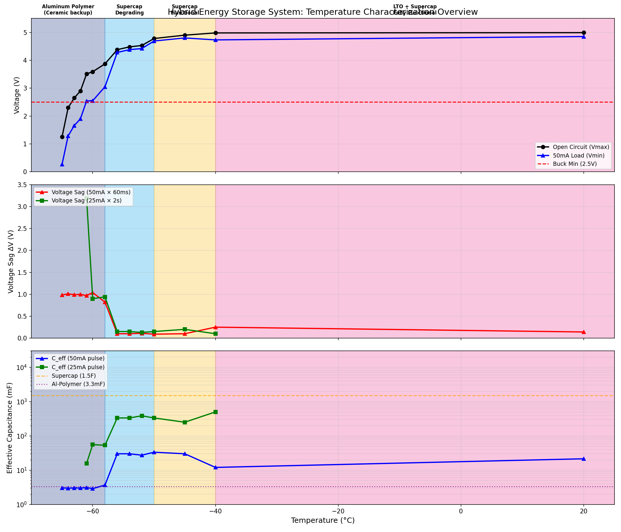
Results: The Temperature Cascade
The test data reveals clean transitions between operating regimes:
Regime 1: Full System Functional (+20°C to -40°C)
| Temp | V_open | V_load (50mA/60ms) | V_load (25mA/2s) | ΔV (short) | ΔV (long) |
|---|---|---|---|---|---|
| +20°C | 4.99V | 4.85V | — | 0.14V | — |
| -40°C | 4.98V | 4.73V | 4.82V | 0.25V | 0.16V |
Behavior: All three layers work together. The LTO battery can supply current directly. Supercap provides buffering. Aluminum polymer is essentially idle—the system doesn’t need it yet.
Effective impedance: 0.14V / 50mA = 2.8Ω at +20°C
Regime 2: Supercapacitor Functional (-40°C to -50°C)
| Temp | V_open | V_load (50mA/60ms) | V_load (25mA/2s) | ΔV (short) | ΔV (long) |
|---|---|---|---|---|---|
| -45°C | 4.94V | 4.80V | 4.74V | 0.14V | 0.20V |
| -50°C | 4.78V | 4.69V | 4.63V | 0.09V | 0.15V |
Behavior: The supercap’s 1.5F easily absorbs short pulses (2mV theoretical sag). Long pulses show the battery ESR increasing—more voltage sag on sustained loads.
Key observation: Short pulses have less sag than long pulses. This is the supercap doing its job—buffering transient demands while the battery struggles with sustained current.
Regime 3: Supercapacitor Degrading (-50°C to -58°C)
| Temp | V_open | V_load (50mA/60ms) | V_load (25mA/2s) | ΔV (short) | ΔV (long) |
|---|---|---|---|---|---|
| -52°C | 4.53V | 4.42V | 4.39V | 0.11V | 0.14V |
| -54°C | 4.48V | 4.38V | 4.33V | 0.10V | 0.15V |
| -56°C | 4.38V | 4.28V | 4.21V | 0.10V | 0.17V |
Behavior: The supercap ESR is increasing but not yet catastrophic. Short pulses remain well-buffered. The aluminum polymer capacitor begins contributing to pulse delivery as supercap ESR rises.
The transition zone: Between -50°C and -58°C, the system gracefully shifts from supercap-dominated to aluminum-polymer-dominated pulse response.
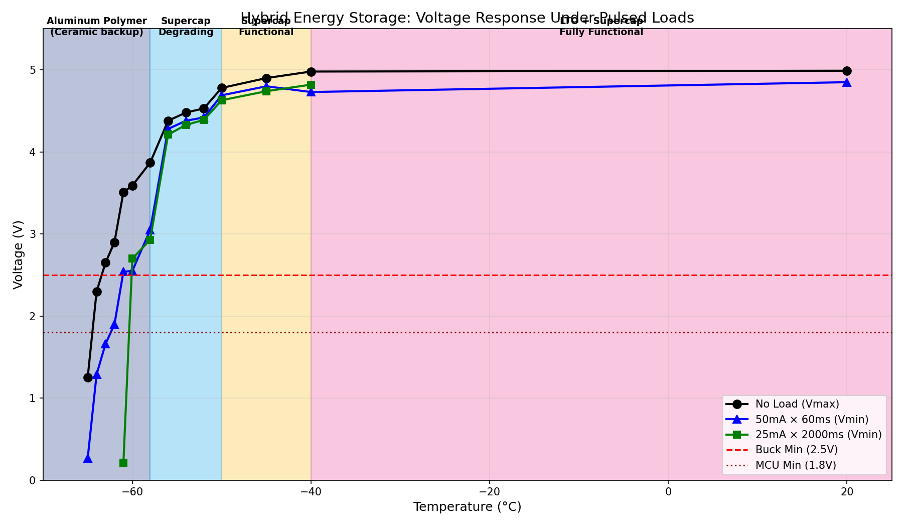
Regime 4: Supercapacitor Failed, Aluminum Polymer Takeover (-58°C to -65°C)
| Temp | V_open | V_load (50mA/60ms) | V_load (25mA/2s) | ΔV (short) | ΔV (long) |
|---|---|---|---|---|---|
| -58°C | 3.87V | 3.05V | 2.93V | 0.82V | 0.94V |
| -60°C | 3.60V | 2.55V | 2.70V | 1.05V | 0.90V |
| -61°C | 3.51V | 2.54V | 0.21V | 0.97V | 3.30V |
| -62°C | 2.90V | 1.90V | — | 1.00V | — |
| -64°C | 2.30V | 1.29V | — | 1.01V | — |
| -65°C | 1.25V | 0.27V | — | 0.98V | — |
The critical data point at -61°C:
- Short pulse (50mA × 60ms): V_load = 2.54V ✓ (marginal but usable)
- Long pulse (25mA × 2s): V_load = 0.21V ✗ (complete collapse)
This is NOT a surprise—it’s ESR vs capacitance in pure form:
Short pulse (3mC extraction): $ \Delta V = \frac{Q}{C} = \frac{3mC}{3.3mF} = 0.91V $
The measured 0.97V matches almost exactly. The aluminum polymer capacitor successfully delivers the RF transmission burst. The 50mA pulse flows through the aluminum polymer’s ~20Ω cold ESR without collapse.
Long pulse (50mC extraction): $ \Delta V = \frac{Q}{C} = \frac{50mC}{3.3mF} = 15V $
Impossible—the capacitor would need to go negative. Instead, within ~200ms the aluminum polymer is depleted. The remaining current (25mA × 1.8s) must flow through:
- Frozen supercap ESR: ~50-100Ω
- Frozen LTO battery: ~100+Ω per cell = 200Ω+
Total path resistance: ~300Ω. At 25mA: V_drop = 7.5V. From 3.5V open circuit → collapse to near zero.
The architecture works: Short RF transmission bursts succeed because the aluminum polymer capacitor delivers the pulse. Sustained loads fail because the frozen supercap and battery cannot replenish the aluminum polymer fast enough.
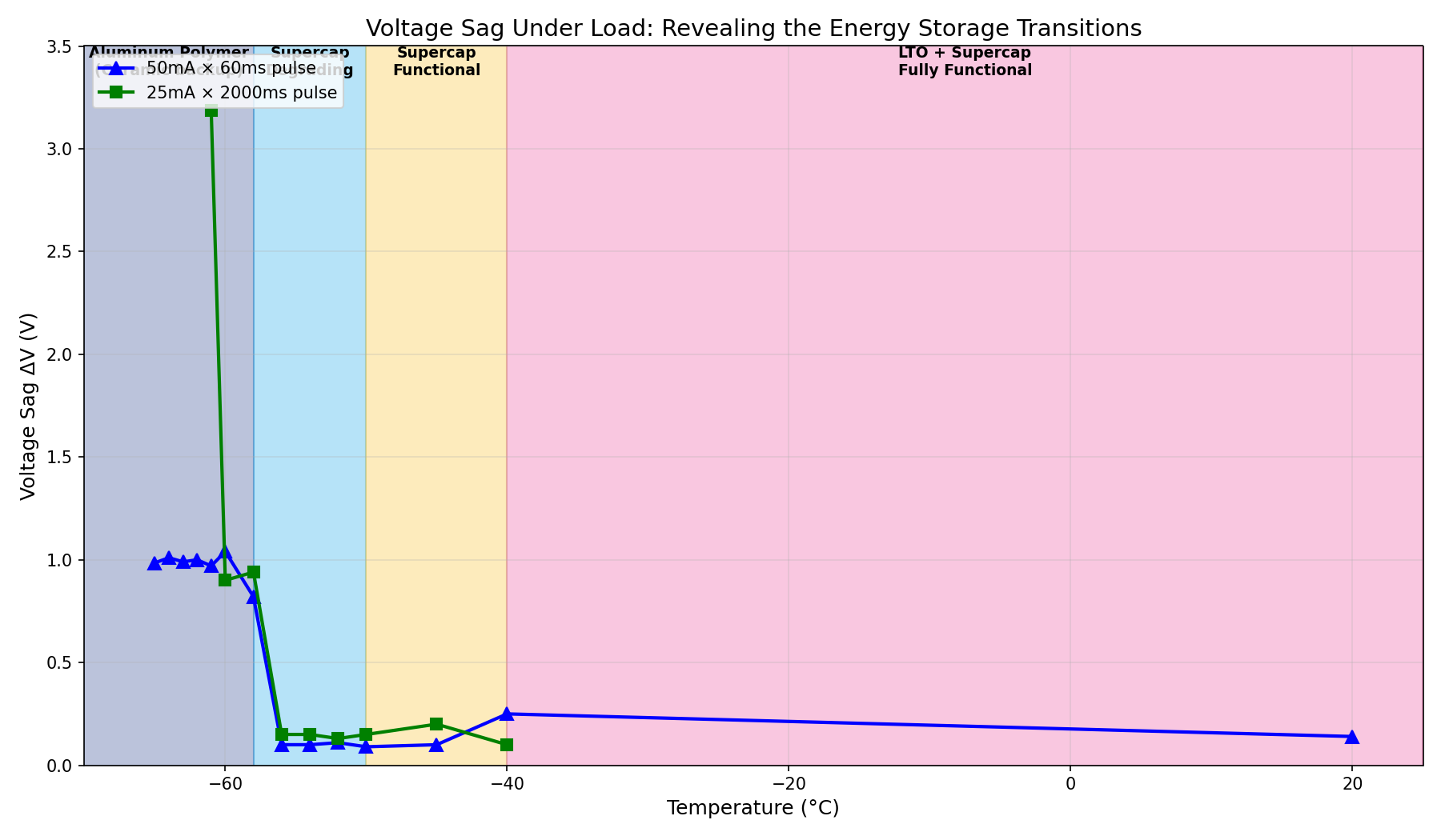
The ESR vs Capacitance Story
The divergence between short-pulse and long-pulse behavior tells the complete story:
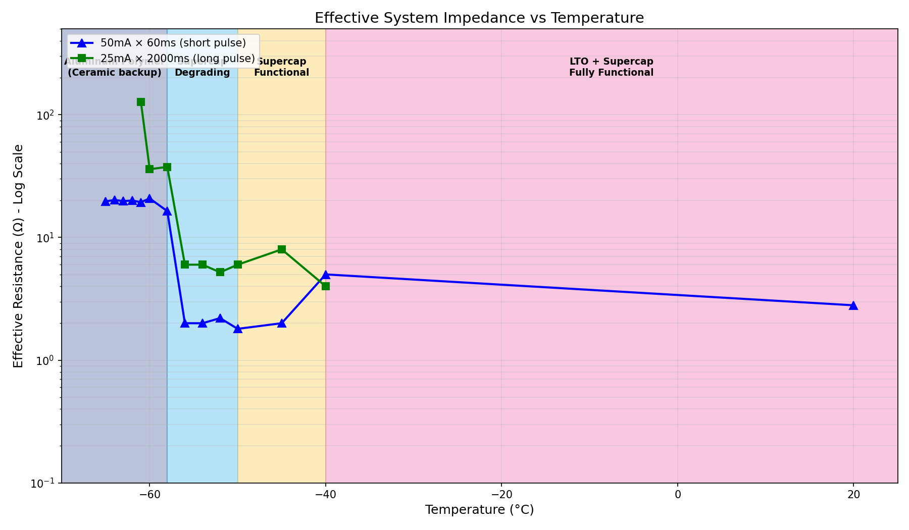
Effective resistance: R_eff = ΔV / I
| Temp | R_eff (50mA/60ms) | R_eff (25mA/2s) | Interpretation |
|---|---|---|---|
| +20°C | 2.8Ω | — | Low impedance, healthy system |
| -40°C | 5.0Ω | 4.0Ω | Slight increase, all layers functional |
| -50°C | 1.8Ω | 6.0Ω | Short pulse: capacitive; long pulse: resistive |
| -56°C | 2.0Ω | 6.8Ω | Divergence begins |
| -58°C | 16.4Ω | 37.6Ω | ESR cliff |
| -60°C | 21.0Ω | 36.0Ω | Aluminum polymer dominant for short pulses |
| -61°C | 19.4Ω | 132Ω | Short pulses work; long pulses impossible |
| -65°C | 19.7Ω | — | At OCV limit |
Key insight: The short-pulse resistance (50mA/60ms) stabilizes at ~20Ω from -58°C to -65°C. This is the aluminum polymer’s cold ESR—high but manageable for 60ms RF bursts, delivering:
$ P_{delivered} = V_{load} \times I = 2.5V \times 50mA = 125mW $
For a minimal SF7 packet requiring ~100mW for 60ms, this works.
The long-pulse resistance explodes from 37Ω at -60°C to 132Ω at -61°C because:
- Aluminum polymer depletes within ~200ms (Q = 3.3mF × 3V = 10mC at 50mA = 200ms)
- Remaining 1800ms must flow through frozen supercap + battery
- Combined ESR > 100Ω causes voltage collapse
Effective Capacitance Analysis
The effective capacitance reveals which component is doing the work:
$ C_{eff} = \frac{I \times t}{\Delta V} $
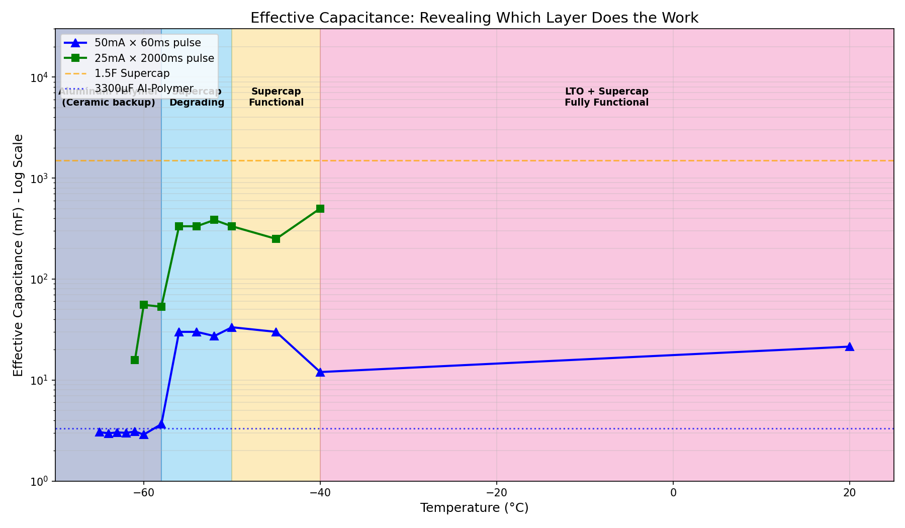
| Temp | C_eff (50mA/60ms) | C_eff (25mA/2s) | Interpretation |
|---|---|---|---|
| +20°C | 21 mF | — | Battery + supercap contributing |
| -40°C | 12 mF | 312 mF | Supercap buffers long pulses |
| -50°C | 33 mF | 333 mF | Supercap dominant |
| -56°C | 30 mF | 294 mF | Supercap degrading |
| -58°C | 3.7 mF | 53 mF | Handoff to aluminum polymer |
| -60°C | 2.9 mF | 56 mF | Aluminum polymer only for short pulses |
| -61°C | 3.1 mF | 15 mF | Short: capacitor; long: ESR-dominated |
The handoff at -58°C:
Above -58°C: C_eff > 10mF (supercap + battery contributing) Below -58°C: C_eff ≈ 3mF (aluminum polymer only)
The 3.3mF aluminum polymer shows up exactly as expected—effective capacitance matches the component value when it becomes the sole functional capacitor.
Power Delivery Capability
The practical question: can we transmit at stratospheric temperatures?
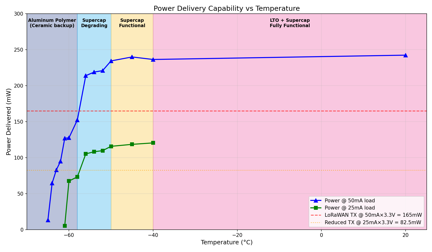
LoRaWAN Requirements:
- Standard transmission: 50mA × 3.3V = 165mW for 100-200ms
- Reduced SF7 transmission: 50mA × 3.3V = 165mW for 60ms
Power delivered at load voltage (P = V_load × I):
| Temp | Power (50mA pulse) | Power (25mA pulse) | Capability |
|---|---|---|---|
| +20°C | 243 mW | — | Full power |
| -40°C | 237 mW | 121 mW | Full power |
| -50°C | 235 mW | 116 mW | Full power |
| -56°C | 214 mW | 105 mW | Full power |
| -58°C | 153 mW | 73 mW | Marginal |
| -60°C | 128 mW | 68 mW | SF7 only |
| -61°C | 127 mW | 5 mW | Short pulses only |
| -64°C | 65 mW | — | Below minimum |
| -65°C | 13 mW | — | Failed |
The operating envelope:
| Temperature | Transmission Mode | Notes |
|---|---|---|
| Above -50°C | Full power SF10/SF12 | All layers functional |
| -50°C to -58°C | SF7-SF10 | Supercap buffering |
| -58°C to -61°C | SF7 short burst only | Aluminum polymer takes over |
| Below -61°C | Data logging only | OCV collapse |
Where Aluminum Polymer Fits in the Cascade
The original four-layer cascade becomes five layers with aluminum polymer:
| Layer | Component | Operating Range | Failure Mode |
|---|---|---|---|
| 1 | Solar | Daytime only | No night power |
| 2 | 2S LTO Battery | +25°C to -50°C | ESR → 100Ω+ |
| 3 | 1.5F Supercap | -40°C to -55°C | ESR → 50Ω+ |
| 4 | 3300µF Al-Polymer | -55°C to -63°C | ESR ~20Ω (usable) |
| 5 | Ceramic bank | Below -60°C | OCV collapse |
The aluminum polymer fills the gap between -55°C (supercap death) and -63°C (OCV collapse).
Without aluminum polymer, the system would need to rely entirely on the ceramic bank below -55°C. The ceramic bank is sized for minimum viable transmission (60ms SF7), but the aluminum polymer provides higher capacitance (3.3mF vs ~1.3mF ceramic bank) with acceptable cold ESR.
Design Recommendation
Based on characterization, the hybrid energy storage configuration is validated for stratospheric operation:
Final Configuration:
- 2× HTC1015 LTO cells (2S, 4.8V nominal, 80mAh total)
- 1× 1.5F supercapacitor (5.5V, ~3g)
- 1× 3300µF aluminum polymer (6.3V, ~1g)
- 6× 220µF ceramics (1.32mF bank, 6.3V, ~6g backup)
Firmware Adaptive Transmission:
if (temperature > -50°C):
    mode = FULL_POWER          # SF10-SF12, any duration
elif (temperature > -58°C):
    mode = SUPERCAP_BUFFERED   # SF7-SF10, up to 200ms
elif (temperature > -63°C):
    mode = ALUMINUM_POLYMER    # SF7 only, 60ms max
else:
    mode = DATA_LOGGING        # No transmission, log to flash
Conclusion: The Bridge Layer Works
The 3300µF aluminum polymer capacitor fills a critical gap in the cascading power architecture:
- Supercap fails at -55°C with ESR increasing to 50+Ω
- Aluminum polymer maintains ~20Ω ESR at -60°C—high but usable for 60ms pulses
- Battery OCV collapse at -63°C sets the absolute floor
- The aluminum polymer extends usable transmission by ~8°C beyond supercap failure
The ESR vs capacitance behavior is exactly as expected:
- Short pulses (60ms): Dominated by capacitance → aluminum polymer (3.3mF) delivers successfully
- Long pulses (2s): Dominated by ESR → frozen supercap/battery cannot sustain → collapse
For the standard stratospheric temperature of -56.5°C, the system operates in the aluminum-polymer-assisted regime with ~6°C margin to failure. The hybrid stack provides graceful degradation rather than hard failure.
The aluminum polymer addition costs 1g and ~$0.50. It extends the operating envelope by 8°C. That’s 0.125°C per cent—arguably the best value component in the entire power system.
Addendum: Leakage Current Investigation — Why the Aluminum Polymer Capacitor Was Removed from the Design
After completing the initial characterization above, an anomaly in the test data prompted further investigation. The conclusion: the aluminum polymer capacitor introduces unacceptable parasitic losses and has been removed from the Stratosonde design. This section documents the failure analysis and lessons learned.
The Anomaly: Lower OCV During Testing
During the aluminum polymer characterization, the LTO cell open-circuit voltage (OCV) was consistently lower than observed in previous test runs at comparable temperatures. At first, this was dismissed as normal variation—but the magnitude of the discrepancy warranted investigation.
Cross-Test OCV Comparison (2S LTO Configuration):
| Temperature | Ceramic Bank Test | LTO+Supercap Test | Aluminum Polymer Test | Discrepancy |
|---|---|---|---|---|
| -50°C | — | 5.09V | 4.78V | −6% |
| -55°C | 5.07V | 5.05V | ~4.48V | −11% |
| -58°C | — | — | 3.87V | — |
| -60°C | 4.70V | 4.90V | 3.60V | −23% to −26% |
| -65°C | 3.33V | — | 1.25V | −62% |
The aluminum polymer test showed substantially lower OCV at every overlapping temperature point. At -60°C, the discrepancy exceeds 1V—a significant fraction of the total battery voltage.
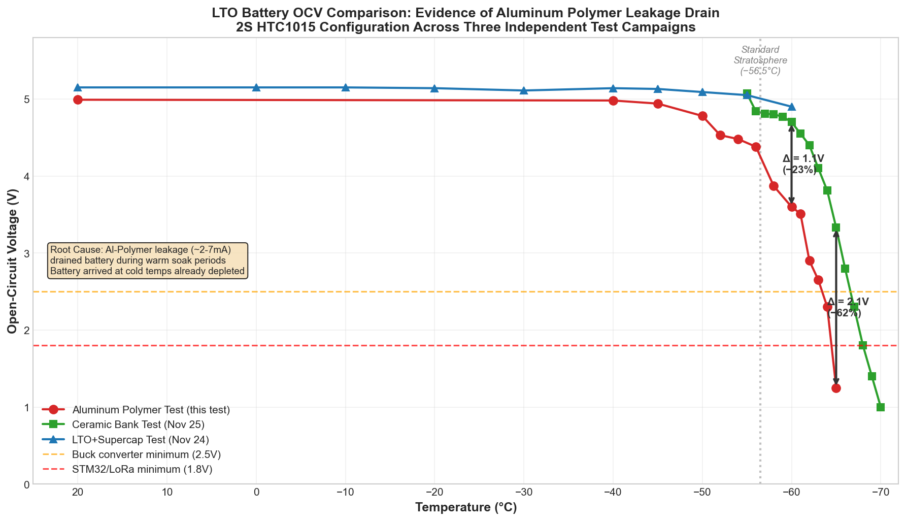
The plot above makes the discrepancy visually unmistakable: while the ceramic bank test and LTO+supercap test show nearly identical OCV curves (both starting ~5.1V and following similar degradation), the aluminum polymer test curve is shifted dramatically lower—especially at the extreme cold temperatures where we need every millivolt.
Root Cause: Aluminum Polymer Leakage Current
The Kyocera RPF1014332M006K datasheet specifies a maximum leakage current of 4.4mA at rated voltage (6.3V) and room temperature. This specification was noted during component selection but underestimated in its impact.
To quantify the actual leakage behavior, a dedicated characterization was performed across temperature and voltage:
Measured Leakage Current (mA) vs Temperature and Voltage:
| Temp (°C) | 2.5V | 3.0V | 3.5V | 4.0V | 4.5V | 5.0V | 5.5V |
|---|---|---|---|---|---|---|---|
| +20 | — | — | — | — | — | — | 7.54 |
| +10 | 0.23 | 0.36 | 0.54 | 0.78 | 1.14 | 1.87 | 5.36 |
| 0 | 0.21 | 0.33 | 0.50 | 0.74 | 1.14 | 1.65 | 3.86 |
| −20 | 0.19 | 0.29 | 0.44 | 0.65 | 0.95 | 1.40 | 2.50 |
| −40 | 0.17 | 0.27 | 0.40 | 0.58 | 0.85 | 1.24 | 1.98 |
| −50 | 0.16 | 0.25 | 0.38 | 0.57 | 0.80 | 1.17 | 1.79 |
| −60 | 0.16 | 0.25 | 0.37 | 0.54 | 0.78 | 1.13 | 1.70 |
| −70 | 0.12 | 0.19 | 0.28 | 0.40 | 0.57 | 0.30 | 1.13 |
Key Observations:
-
Room temperature leakage exceeds datasheet maximum: At 5.5V and +20°C, measured leakage was 7.54mA—72% above the 4.4mA maximum specification. The datasheet specification applies at 6.3V; extrapolating to 5.5V should yield lower leakage.
-
Leakage is strongly voltage-dependent: At −60°C, leakage drops from 1.70mA (at 5.5V) to 0.54mA (at 4.0V)—a 3× reduction. This exponential voltage dependence is characteristic of aluminum electrolytic leakage mechanisms.
-
Temperature reduces leakage significantly: From +20°C to −60°C at 5.5V, leakage drops from 7.54mA to 1.70mA—a 4.4× improvement. Cold temperatures slow the electrochemical processes responsible for leakage.
-
Even cold leakage is substantial: At typical 2S LTO operating voltage (~4.5V) and stratospheric temperature (−60°C), leakage is still 0.78mA continuous.
Impact Analysis: The Double Penalty
The aluminum polymer capacitor imposes a double penalty on the power system:
Penalty 1: Warm-Weather Battery Drain
During the aluminum polymer test, the 2-hour thermal soak at each temperature allowed continuous leakage current:
At +20°C to −40°C (warm regime where supercap is functional):
- Average leakage: ~2-5mA
- Drain per 2-hour soak: 4-10mAh
- Cumulative drain across warm soak points: ~20-30mAh
For a 40mAh LTO cell pack, this represents 50-75% of total capacity lost to leakage before reaching the extreme cold temperatures where the aluminum polymer was supposed to provide benefit.
Penalty 2: Depleted Battery When Most Needed
The lower OCV observed at extreme cold (−58°C to −65°C) directly results from the warm-weather drain:
| Test | OCV at −60°C | Probable Cause |
|---|---|---|
| Ceramic bank test | 4.70V | Fresh battery, no aluminum cap leakage |
| LTO+Supercap test | 4.90V | Fresh battery, no aluminum cap leakage |
| Aluminum polymer test | 3.60V | Battery depleted by 30+ mAh of warm leakage |
The 1.1-1.3V lower OCV at −60°C directly translates to reduced transmission capability—exactly when the aluminum polymer was supposed to bridge the gap between supercap failure and ceramic operation.
The Datasheet Warning We Ignored
The 4.4mA maximum leakage specification was visible from the start. For a 40mAh battery pack, this represents:
$ t_{drain} = \frac{Q_{battery}}{I_{leakage}} = \frac{40mAh}{4.4mA} = 9.1 \text{ hours} $
A fully charged battery would be completely drained in under 10 hours from aluminum polymer leakage alone—even with no other loads.
The error was assuming that cold temperatures would eliminate the leakage concern. While cold reduces leakage (to ~0.8-1.7mA at stratospheric temperatures), the damage occurs during the warm phase:
- Ground handling at room temperature
- Initial ascent through temperate troposphere
- Thermal chamber soak periods during testing
By the time the balloon reaches extreme cold altitudes where the aluminum polymer’s low ESR matters, the battery has already been significantly depleted.
Why Not Just Disconnect the Aluminum Cap When Warm?
A theoretical mitigation would be to use a MOSFET switch to disconnect the aluminum polymer capacitor during warm operation and only engage it below −50°C when the supercap fails.
Problems with this approach:
- Added complexity: Switch, gate driver, temperature-based control logic
- Switch resistance: Even a good MOSFET adds 10-50mΩ in the critical power path
- Failure modes: Switch stuck open → no cold operation; stuck closed → original problem
- Mass penalty: ~0.5g for switch components, negating the 1g aluminum polymer
The complexity isn’t justified when a simpler solution exists.
The Alternative: Larger Ceramic Capacitor Bank
The ceramic capacitor bank tested previously demonstrated excellent performance to −70°C with zero leakage current. The limitation was sizing—the original 408µF bank was deliberately undersized to expose the supercap-to-ceramic transition.
Revised ceramic-only architecture:
| Parameter | Original Design | Revised Design |
|---|---|---|
| Ceramic bank size | 1.32mF (6× 220µF) | 2.2mF (10× 220µF) |
| Mass | 6g | 10g |
| Leakage current | 0 | 0 |
| ESR at −60°C | <50mΩ | <50mΩ |
| Cost | ~$3 | ~$5 |
| Operating range | −55°C to −65°C | −55°C to −65°C |
The 4g mass penalty (10g vs 6g) is offset by removing the 1g aluminum polymer capacitor, yielding a net increase of only 3g.
Critically: Zero leakage means the battery arrives at extreme cold temperatures at full state-of-charge, maximizing the available energy for transmission.
Lessons Learned
-
Leakage specifications matter for small batteries: A “mere” 4.4mA leakage is catastrophic for a 40mAh battery pack. Always calculate drain time: $t = Q/I$.
-
Warm-weather parasitic losses compound: Components that operate during warm portions of the mission profile drain energy that’s desperately needed later.
-
Cold-temperature benefits don’t erase warm-temperature costs: The aluminum polymer’s improved cold performance was irrelevant because the battery was already depleted.
-
Solid dielectrics > liquid/polymer electrolytes for extreme environments: Ceramic capacitors have zero leakage because they use solid ceramic dielectric. No liquid = no leakage paths.
-
The datasheet tried to warn us: The 4.4mA maximum leakage was right there. Component selection should have included a power budget analysis showing this was incompatible with the battery capacity.
Revised Conclusion: Component Rejected
The aluminum polymer capacitor Kyocera RPF1014332M006K is not suitable for the Stratosonde cascading power architecture. While its cold-temperature ESR performance is adequate, the continuous leakage current creates an unacceptable energy loss that defeats its intended purpose.
Revised Final Configuration:
- 2× HTC1015 LTO cells (2S, 4.8V nominal, 80mAh total)
- 1× 1.5F supercapacitor (5.5V, ~3g)
1× 3300µF aluminum polymer (6.3V, ~1g)REMOVED- 10× 220µF ceramics (2.2mF bank, 6.3V, ~10g)
The ceramic bank absorbs the aluminum polymer’s intended role with no parasitic losses, proven extreme-cold performance, and only 3g additional mass.
Firmware Adaptive Transmission (revised):
if (temperature > -50°C):
    mode = FULL_POWER          # SF10-SF12, any duration
elif (temperature > -55°C):
    mode = SUPERCAP_BUFFERED   # SF7-SF10, up to 200ms
elif (temperature > -65°C):
    mode = CERAMIC_ONLY        # SF7 only, 60ms max
else:
    mode = DATA_LOGGING        # No transmission, log to flash
This experience reinforces a fundamental principle of space-constrained, energy-limited system design: every milliamp counts, especially the ones you can’t see.
Related Posts
This post is part of the Stratosonde power system characterization series:
- HTC1015 LTO Temperature Characterization - Individual cell testing
- BQ25570 Bench Characterization - Solar energy harvester efficiency
- Stratosonde Cascading Power Architecture - The multi-layer power design
- Ceramic Capacitor Bank Validation - Ceramic layer at -70°C
Test configuration: 2× HTC1015 LTO cells in series, 1.5F supercapacitor (5.5V), 3300µF aluminum polymer capacitor, all in parallel. Load profiles: 50mA × 60ms and 25mA × 2000ms.
Raw characterization data: aluminum_polymer_capacitor_test.csv
Leakage current characterization data: aluminum_polymer_leakage_test.csv